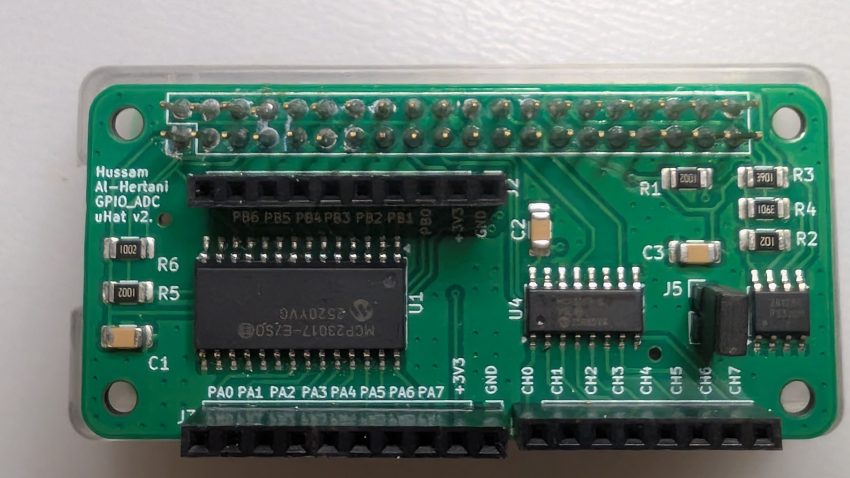
In this blog entry, I will introduce my IO μHat (microHat) for the Raspberry Pi Zero 2W. This particular μHat provides:
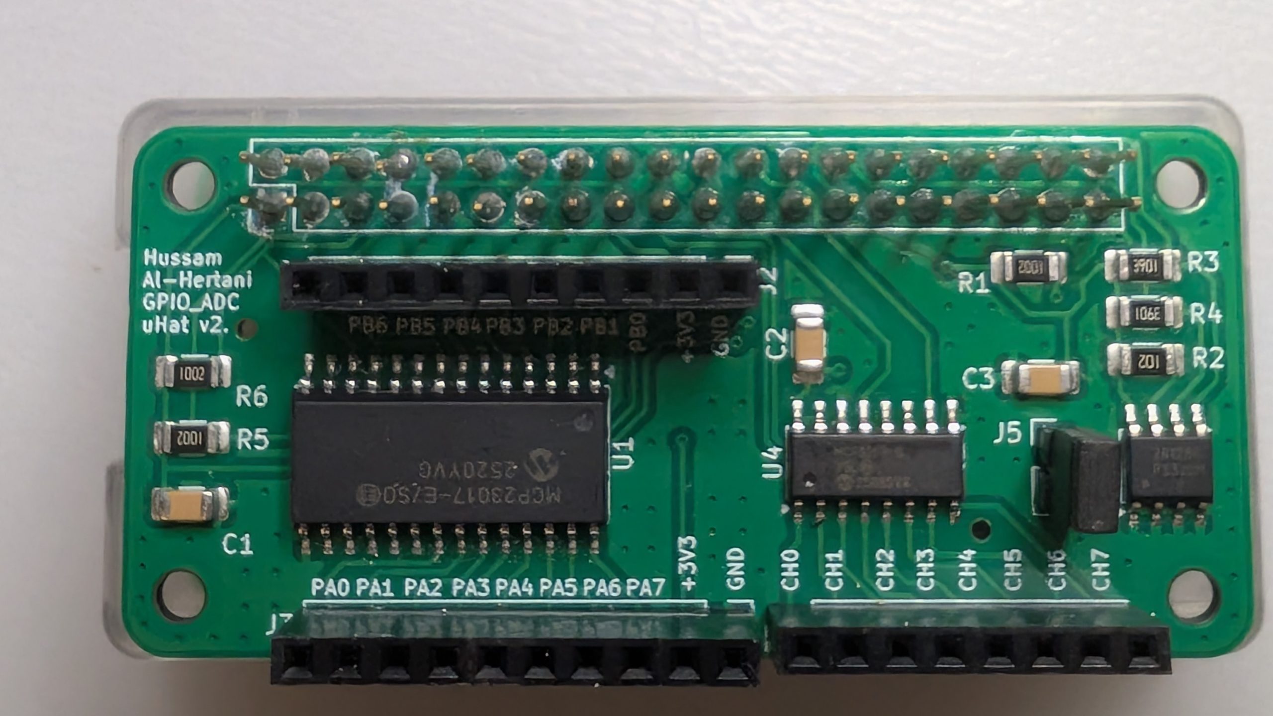
- The MCP23017 I2C GPIO expander, providing an additional 16 general-purpose input output pins (GPIOs)
- The MCP3208 SPI ADC; providing an 8 channel, 12-bit analog-to-digital convertor (ADC)
The IO μHat also hosts an I2C EEPROM as per the μHat specifications. The configuration of this EEPROM will be covered in a future entry.
The schematic is shown below:
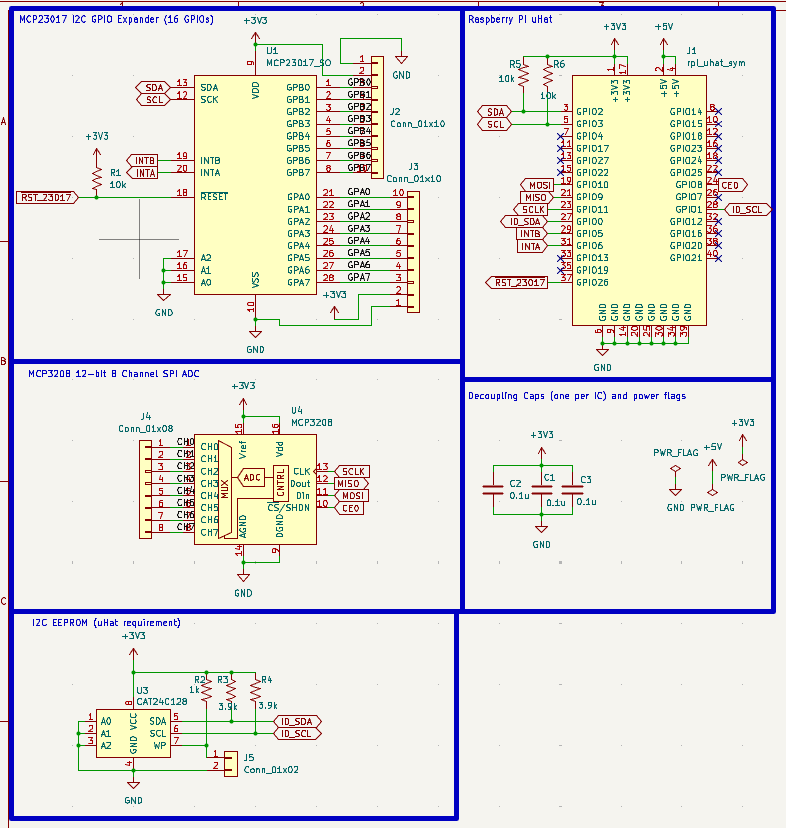
Both the GPIO expander and ADC chips are powered from the +3.3V rail. This means the GPIO expander can only accept +3.3V signals as an input. The ADC’s reference voltage is also set to +3.3V.
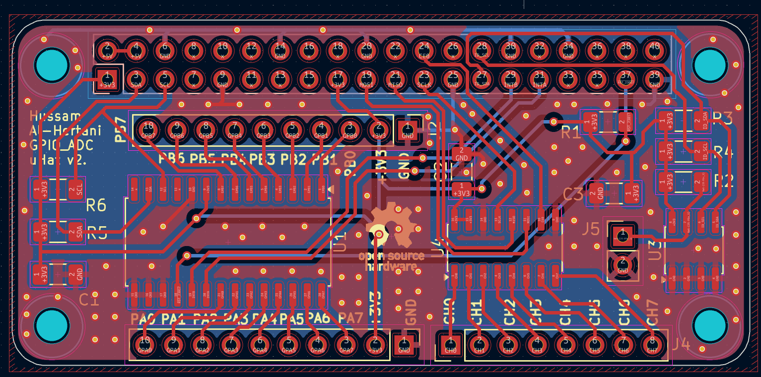
The IO μHat was designed to be easy to hand-solder, utilizing SOIC packages for all the ICs and larger 1206 packages for the resistors and capacitors. The layout for IO μHat is shown below:
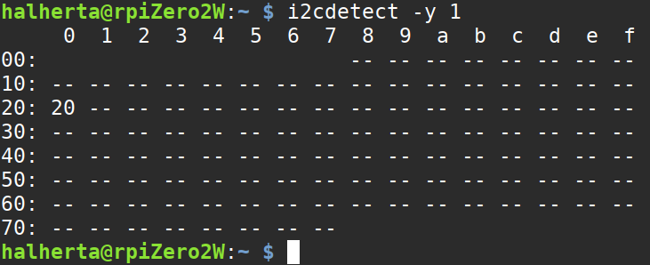
When probing the I2C bus on the Raspberry Pi Zero 2W, I was successfully able to detect the GPIO expander with an address of 0x20:
I also wrote two Python classes that control the MCP23017’s GPIOs and perform ADC conversions with the MCP3208. A demo program is also available in the GitHub repository.
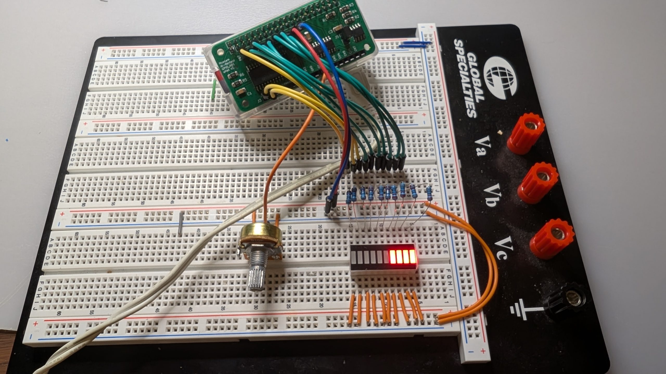
The demo program reads the incoming analog voltage from the potentiometer wiper pin and turns on a proportional number of LEDs on the bargraph. So when the potentiometer wiper voltage is at 0V, all 10 LEDs are OFF. When the potentiometer wiper voltage is at 3.3V, all 10 LEDs are ON, and so on.
As usual, my IO μHat KiCad design files are all freely available on my GitHub repository. I’m planning to write a few more blog entries about this board, so stay tuned!
Leave a comment if you are interested in purchasing an IO μHAT board! I’m considering making a few and selling them on TIndie in the near future.