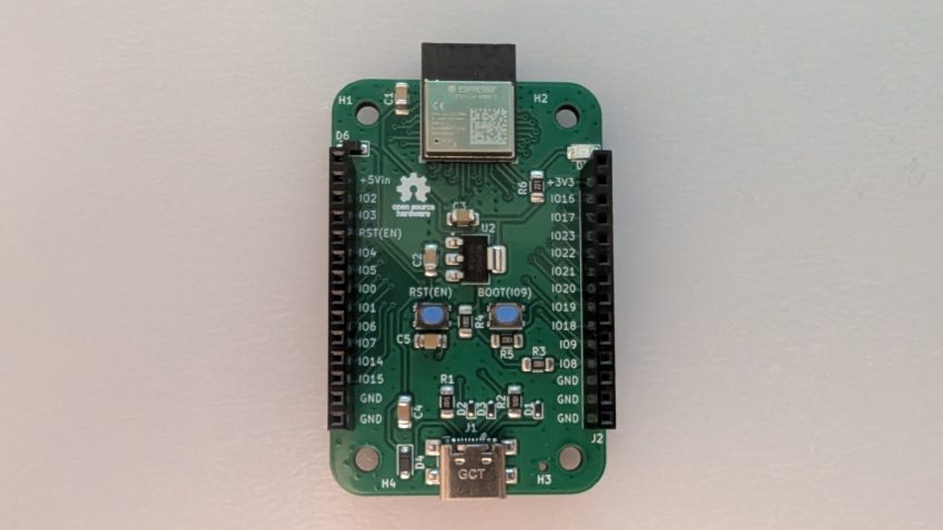
IoTLynx is a new microcontroller development board based on Espressif’s ESP32-C6 microcontroller (ESP32-C6-MINI-1module). Designed with accessibility in mind, the IoTLynx platform caters to makers, hobbyists, and newcomers to programming and electronics. Though the board supports C programming, it was specifically designed to run MicroPython—a choice that aligns with its philosophy of ease of use. With the MicroPython REPL pre-loaded and ready to run, users can start coding immediately without the hassle of configuring development environments or installing IDEs.
IoTLynx Pinout
The IOTLynx pinout diagram is shown in the Figure below.
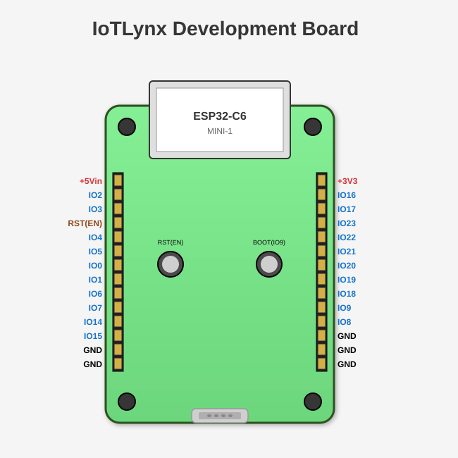
Power can be applied to the board via the ‘+5Vin’ pin (use a +5V source only) or via USB-C connector. You can apply power via the ‘+5Vin’ pin AND still have the USB-C connector attached at the same time in case you need to view serial output over USB. The board also provides a +3V3 output power rail.
ESP32-C6 Specifications
The ESP32C6 (ESP32-C6-MINI-1) specifications are summarized below:
CPU & Memory
- Processor: RISC-V 32-bit single-core processor, up to 160 MHz
- RAM: 512 KB SRAM (high-performance)
- ROM: 320 KB ROM
- Flash: 4 MB embedded flash (in the module)
Wireless Connectivity
- Wi-Fi: 802.11 b/g/n (2.4 GHz), supports Wi-Fi 6 features
- Bluetooth: Bluetooth 5.3 (LE)
- Zigbee: IEEE 802.15.4 (Thread/Zigbee protocol support) – Not supported in MicroPython
- 6LoWPAN: Support for low-power wireless networking – Not supported in MicroPython
Peripherals & Interfaces
- GPIO: 22 programmable GPIOs (19 available on the IoTLynx board)
- SPI: 2x SPI interfaces
- UART: 2x UART interfaces
- I2C: 1x I2C interface
- I2S: 1x I2S interface for audio
- LED PWM: 6 channels
- ADC: 7-channel 12-bit SAR ADC
- GPIO interrupt: All GPIOs support
- Capacitive touch: 7 channels
- Temperature sensor: Built-in
- USB: USB 2.0 full-speed (OTG)
- JTAG: On-chip debugging support
Security Features
- Hardware encryption accelerators (AES, SHA, RSA, ECC)
- Secure boot
- Flash encryption
- Digital signature peripheral
- Random number generator (RNG)
Power
- Operating voltage: 3.0V to 3.6V
- Multiple low-power modes
- Active mode (Wi-Fi): ~95 mA
- Modem-sleep: ~15 mA
- Light-sleep: ~3 mA
- Deep-sleep: ~7-10 µA
Module Physical Specifications
- Dimensions: 13.2 mm × 16.6 mm × 2.4 mm
- Package: SMD-37 (castellated holes)
- Antenna: PCB on-board antenna
- Pins on module: 37 pins total
The ESP32-C6 is particularly well-suited for IoT applications requiring Wi-Fi 6 and Bluetooth LE connectivity in a compact, low-power package.
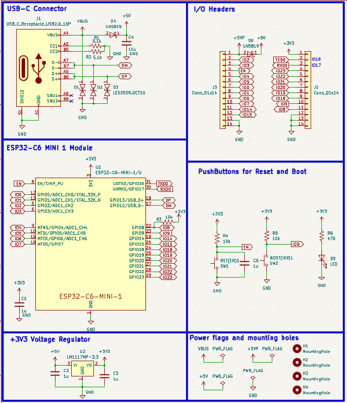
IoTLynx Schematic
The IoTLynx board brings out all of the ESP32-C6-MINI-1 module’s GPIOs, except the USB pins. Power and GPIO pins are brought out to two 14-pin female headers for easy access. The board comes with RESET & BOOT pushbuttons, a USB-C connector for programming and serial port output, a +3V3 regulator, and an LED power-on indicator. The schematic for the IoTLynx is shown below.
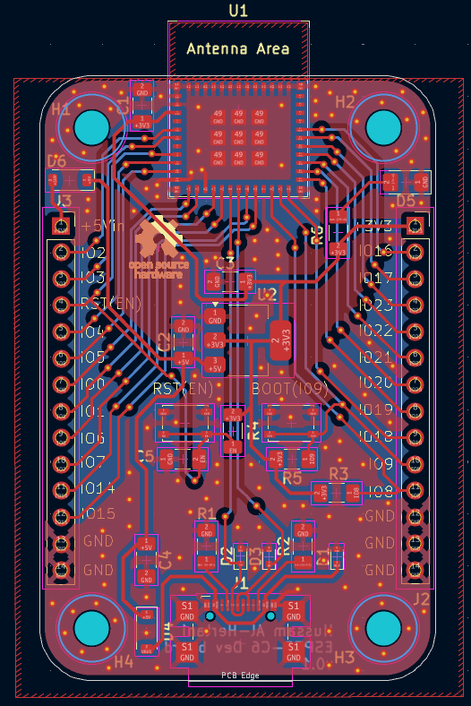
IoTLynx PCB Layout
The IoTLynx development board is 58mm by 38mm in size with rounded edges. It brings out 20 GPIOs (including BOOT(IO9)) via headers J2 & J3.
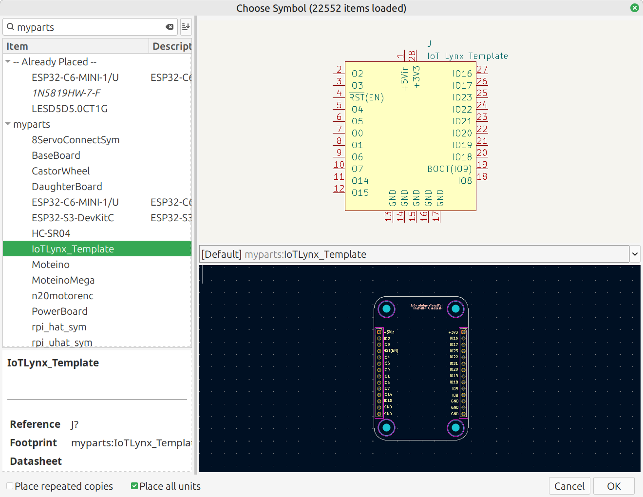
The board is designed to have add-on boards attached above it via the two female header connectors, much like Arduino shields or Raspberry Pi hats. A schematic/footprint template for this add-on board is available in my kicad parts library. These add-on boards are referred to as ‘Top’ boards. I plan to build some in the near future!
The IoTLynx development board was designed as a 2-layer printed circuit board. This significantly reduces PCB fabrication costs. Ground copper fills are applied to both copper layers for increased noise immunity. M3 mounting holes were also mounted on all four corners of the development board. The PCB layout for the IOTLynx is shown in the figure below.
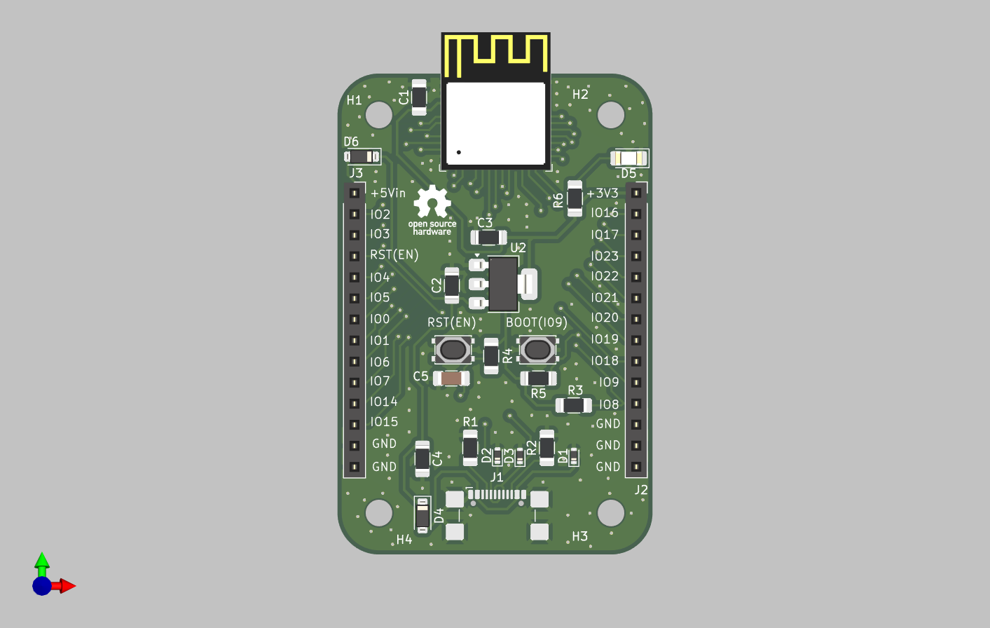
The 3D render of the IoTLynx development board is shown in the Figure below.
Board Bring-up
To start using the board with MicroPython, you’ll need the following prerequisites:
- Thonny (an easy-to-use MicroPython/Python editor and serial port terminal) & esptool(Espressif’s flashing tool)
- The latest MicroPython ESP32-C6 image, which can be downloaded from the official MicroPython website
First, install Thonny and esptool either via pip in a Python virtual environment:
pip install thonny esptool
or via apt on Debian / Ubuntu:
sudo apt install thonny esptool
Next, connect the IoTLynx board to your computer via USB cable and find the enumerated serial port number corresponding to your board. On Windows, it’s usually something like COM3 or COM4 on MS Windows or /dev/ttyUSB0 or /dev/ttyACM0 on Linux/Mac.
You can list available serial ports with:
# Linux/Mac
ls /dev/tty*

# Windows (in PowerShell)
[System.IO.Ports.SerialPort]::getportnames()
Use the esptool to erase the ESP32-C6’s Flash:
esptool --chip esp32c6 --port /dev/ttyUSB0 erase_flash
Be sure to replace /dev/ttyUSB0 with your actual serial port name/label.
At this point, you are ready to flash the MicroPython image onto the IoTLynx’s ESP32C6 module!
esptool --chip esp32c6 --port /dev/ttyUSB0 write_flash -z 0x0 ESP32_GENERIC_C6-XXXXXXXX.bin
Replace ESP32_GENERIC_C6-XXXXXXXX.bin with the actual filename you downloaded.
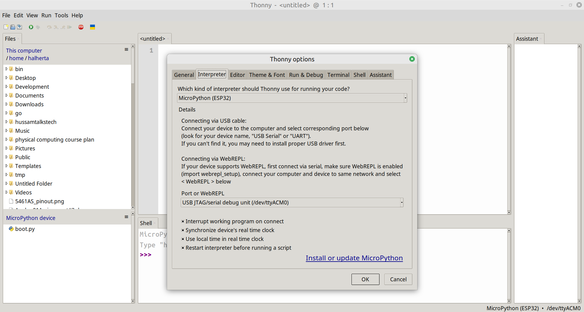
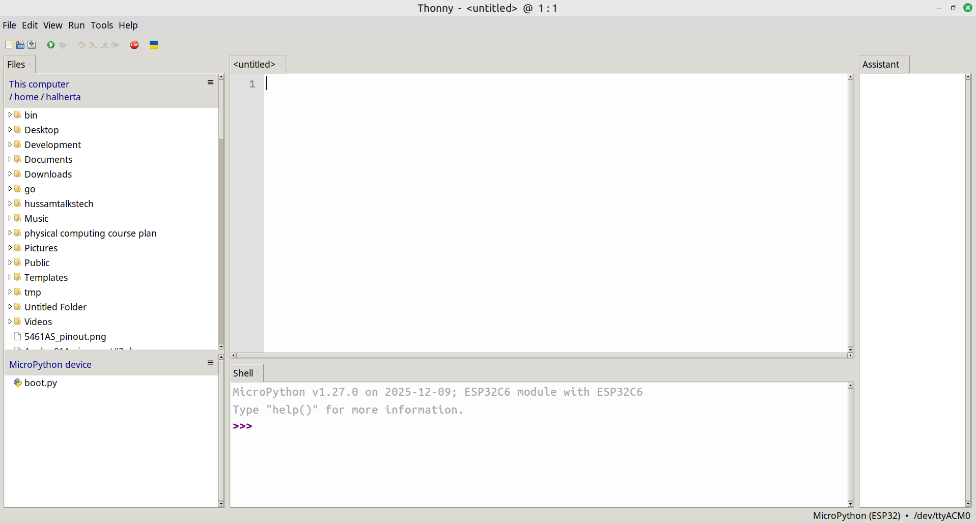
Open Thonny, go to : Run->Configure Interpreter. Select the Interpreter tab as shown in the Figure above. Select from the first dropdown menu “MicroPython (ESP32)”. And select from the second dropdown menu the IoTLynx’s serial port then press OK. If your Thonny IDE is correctly configured, a message will show up in the bottom ‘shell’ window along with the Python REPL prompt:
MicroPython v1.xx.x on 20xx-xx-xx; ESP32C6 module with ESP32C6
Type "help()" for more information.
>>>
Congratulations! You are ready to program your IoTLynx board in MicroPython!
Design Files
The KiCad design files are availble on Github:
- IoTLynx development board
- My parts library containing the IoTLynx ‘Top’ board template (schematic & footprint)
Demo
Here’s a quick video demo of the IoTLynx board controlling an st7789 TFT LCD display! The st7789 TFT LCD MicroPython library and demo code are available here.
I was thinking of selling fully assembled IoTLynx development boards on Tindie. If you’re interested in acquiring an IoTLynx board, let me know in the comments!
Awesome project Hussam! I will definitely grab this to redesign my robot from 3rd year.
***Also, get a tripod for your videos.