
The gpiod library (libgpiod) is the modern, kernel-recommended way to interact with GPIO pins on Linux systems like the Raspberry Pi. The latest 2.x API represents a significant improvement over the older sysfs interface and the 1.x API, offering better performance, cleaner syntax, and more reliable hardware access.
To deepen my understanding of the Linux GPIOD driver and accompanying gpiod Python library, I interfaced a 4-digit seven-segment display module with the Raspberry Pi GPIO pins, and the Python gpiod library.
I will be using the ‘5461AS’ common cathode four-digit, seven-segment (with decimal point) display. The pinout for this display module is shown in the Figure below:

Individual segments within a digit (A-G & DP) can be turned on by setting their corresponding GPIO pin to output HIGH. Controlling a single seven-segment display requires 8 pins, which would mean 32 pins total for four displays—far too many GPIO pins! Fortunately, the 5461AS includes DIG1-4 pins that activate one seven-segment display at a time.
To enable the first display, pull DIG1 pin (12) LOW while keeping the other DIGX pins (9, 8, and 6) HIGH to disable them. Then set the GPIO pins HIGH or LOW for each LED segment (A-G & DP) to display different numbers and characters on that first display.
Repeat this process for each subsequent display: pull DIG2 (9) LOW with others HIGH, then DIG3, then DIG4, then back to DIG1, and so on.
This digit-scanning approach activates only one of the four displays at a time. However, if you alternate the digits faster than 30 times per second, the human eye perceives all four displays as continuously lit. This allows us to control all four displays using just 12 GPIO pins (8+4) instead of 32, exploiting a phenomenon called ‘persistence of vision’.
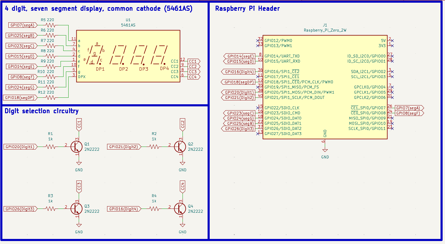
The schematic above shows how I connected the Raspberry Pi to the four-digit seven-segment display. A 220Ω current-limiting resistor sits between each LED segment and its controlling GPIO pin, limiting current per segment to approximately 6mA.
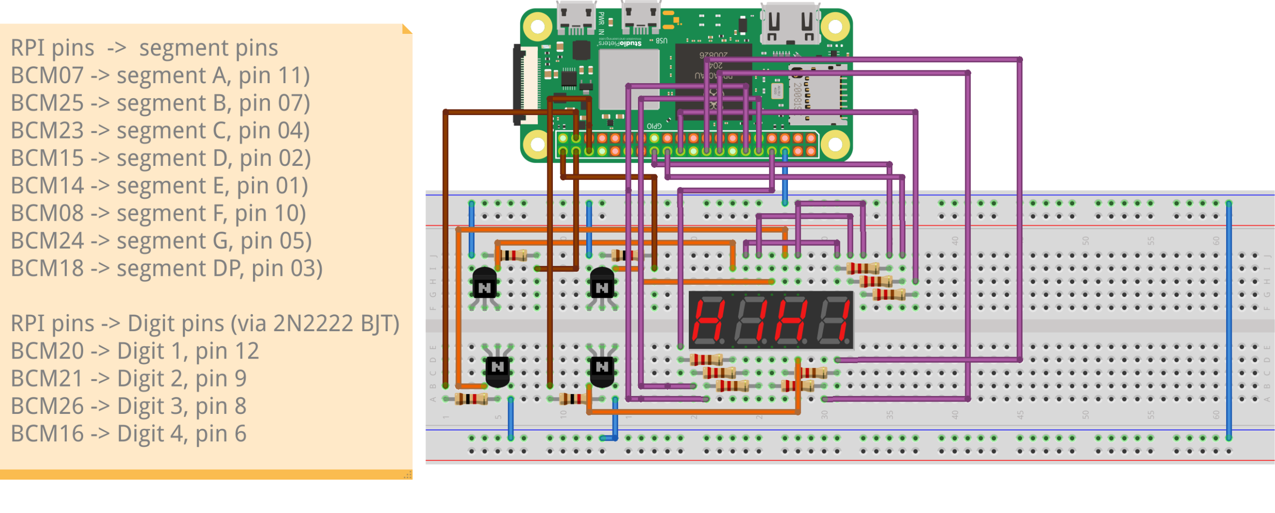
Rather than connecting DIG1-4 pins directly to Raspberry Pi GPIOs, I connected them to ground through transistors controlled by GPIO pins. This prevents up to 48mA (from 8 LEDs) from flowing through a single GPIO pin, which could cause damage. A breadboard wiring diagram is also provided below:
I wrote a quick Python Class ‘FourSevenSeg’ that handles the implementation details. You’ll find this class and some demo code available on my FourSevenSegmentDisplayControl Github repository.
Using the FourSevenSeg class is straightforward. Start by instantiating a FourSevenSeg object, selecting the GPIO I/O block (‘/dev/gpiochip0’), the GPIO pins for controlling segments and digits, and the refresh rate.
# Configure your GPIO pins here
SEGMENT_PINS = [7, 25, 23, 15, 14, 8, 24]  # a, b, c, d, e, f, g
SELECT_PINS = [20, 21, 26, 16]  # digit 1, 2, 3, 4 select pins
DP_PIN = 18  # decimal point pin (optional)

# Initialize the display
display = FourSevenSeg(
    chip="/dev/gpiochip0",
    seven_segment_pins=SEGMENT_PINS,
    dp_pin=DP_PIN,
    select_pins=SELECT_PINS,
    refresh_rate=200  # Hz
)
To start displaying data, call the start() method. Then, create a list of 4 digits from the built-in DIGIT_PATTERNS dictionary and call update_display_data(). A separate update_dp_segment() method is used to update the four decimal places.
display.start()
print("Display started.")

print("\nDisplaying 12.34")
digits = [
    FourSevenSeg.DIGIT_PATTERNS[1],
    FourSevenSeg.DIGIT_PATTERNS[2],
    FourSevenSeg.DIGIT_PATTERNS[3],
    FourSevenSeg.DIGIT_PATTERNS[4]
]
display.update_display_data(digits)
display.update_dp_segment([False, True, False, False])  # DP after digit 2
time.sleep(3)

print("\nClearing display")
blank = [FourSevenSeg.CHAR_PATTERNS[' ']] * 4
display.update_display_data(blank)
display.update_dp_segment([False, False, False, False])
time.sleep(2)
display.close()
When finished, clear each display and turn off all decimal point LEDs, then call the close() method.
A quick video demo of the four-digit, seven-segment display in action!