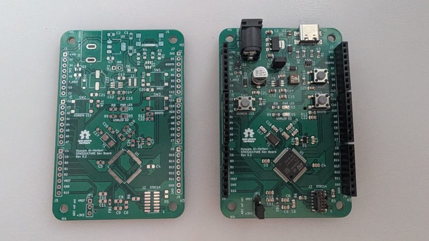
The EmbLynx board is a development board for the STM32G474RE micro-controller. The STM32G474RE is a mainstream ARM Cortex-M4 micro-controller (running up to 170 MHz) heavily optimized as a mixed-signal system-on-chip (SoC). It integrates extensive analog infrastructure alongside math accelerators designed for digital power conversion, motor control, and advanced sensing applications.
Overview of the Peripherals on the STM32G474RE
Beyond its mixed-signal core, the STM32G474RE includes:
- Processing & Memory: ARM Cortex-M4 with FPU and DSP instructions (170 MHz), ART Accelerator (0-wait-state from Flash), 512 KB Dual-Bank Flash (with ECC), 128 KB SRAM (with hardware parity on select blocks), and a 32 KB instruction/data CCM-SRAM routine booster.
- Mathematical Accelerators: CORDIC (for trigonometric and hyperbolic functions) and FMAC (Filter Math Accelerator for FIR/IIR/3p3z compensators).
- Timers: 17 timers in total, including the specialized HRTIM (High-Resolution Timer with 184 ps resolution), advanced motor control timers, general-purpose 32-bit/16-bit timers, basic timers, low-power timers, and watchdogs.
- Connectivity & Comms: 3x FDCAN, 4x I2C (Fast-mode Plus), 5x USART/UARTs, 1x LPUART, 4x SPI / 2x I2S, SAI (Serial Audio Interface), USB 2.0 Full-Speed, and a USB Type-C / USB Power Delivery (UCPD) controller.
- System & Control: 16-channel DMA controller, Flexible Static Memory Controller (FSMC/Quad-SPI), True Random Number Generator (RNG), and CRC unit.
Deep Dive: Mixed-Signal & Analog Peripherals
The analog suite on the STM32G474RE is exceptionally dense; which is precisely why I really like this microcontroller!
1. Analog-to-Digital Converters (ADCs)
- Quantity & Architecture: 5 independent 12-bit SAR ADCs.
- Performance: Conversion rates up to 4 Msps per ADC. Resolution can be extended up to 16-bit via hardware oversampling. Conversion rate can also be extended to 8Msps by interleaving 2 ADCs!
- Key Features: Supports single-ended and differential inputs, internal hardware offset/gain calibration, low aperture time (~20 ns) for precise snapshot/sampling, and simultaneous multi-ADC sampling. They link heavily with the HRTIM for cycle-accurate triggering.
2. Digital-to-Analog Converters (DACs)
- Quantity: 7 DAC channels distributed across multiple converters.
- Configuration:
- 3 Buffered External Channels: Standard 1 MSPS outputs tied to external pins.
- 4 Unbuffered Internal Channels: Ultra-fast 15 MSPS outputs designed to feed internal analog elements (like comparators and op-amps) directly.
- Performance: Settling time down to 16 ns.
3. Operational Amplifiers (OPAMPs)
- Quantity: 6 operational amplifiers.
- Key Features:
- All terminals (inputs/outputs) are fully accessible externally.
- Can be configured dynamically as Programmable Gain Amplifiers (PGAs) with selectable internal gains (e.g., x2, x4, x8, x16, x32, x64, or negative variations).
- High bandwidth (~13 MHz) and high slew rate (45 V/us).
4. Analog Comparators (COMP)
- Quantity: 7 ultra-fast rail-to-rail comparators.
- Performance: Extremely low propagation delay of 16.7 ns.
- Key Features: Programmable hysteresis (8 steps up to 63 mV) and flexible routing to trigger emergency stops or trip events directly inside the motor control and high-resolution timers.
5. Internal Voltage Reference Buffer (VREFBUF)
- Purpose: Provides a stable, accurate internal voltage reference for ADCs and DACs independent of supply fluctuations.
- Features: Supports three selectable preset reference voltages (2.048 V, 2.5 V, and 2.95 V).
6. Temperature Sensor & Internal Channels
Internal reference voltage monitoring channel ($V_{REFINT}$).
An internal temperature sensor connected to ADC channels for thermal monitoring.
EmbLynx development board schematic
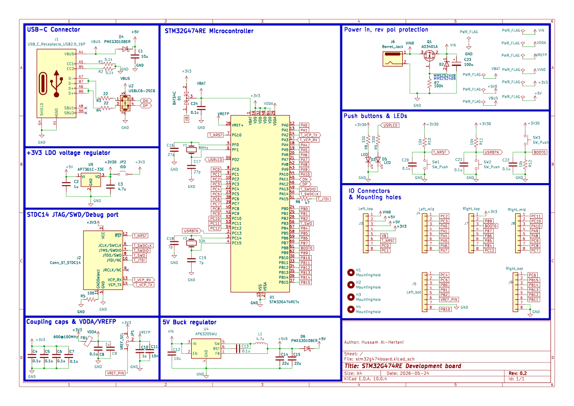
The EmbLynx development board can be powered via a reverse polarity protected DC jack or Vin pin on its I/O headers with a voltage between 6-30V. This is then fed into an AP63205WU 5V buck converter that brings the voltage down to 5V.
Alternatively the board can also be powered by 5V directly via the 5V pins on the I/O header, or via the USB-C (5V) connector. The USB-C connector circuit has TVS diodes and 22 ohm resistors included.
The 5V rail is then passed into a +3V3 LDO regulator to generate the 3.3V rail that powers the STM32G474RE microcontroller.
The board also includes:
- STDC14 SWD/JTAG/Serial debug port for use with an STLinkV3 debugger
- RESET and BOOT0 pushbuttons to facilitate reseting & programming the microcontroller via USB DFU mode.
- User controlled pushbutton (PC13)
- Power LED & user controlled LED (tied to PD2)
- A jumper select for selecting the voltage on the Vref pin to either be +3V3, or another voltage applied via the I/O header.
- Filtering circuitry for the analog VDD and VREF+ pins
- IDD jumper for use to measure the microcontroller’s current consumption.
- BAT54C (dual schottky diodes) used to connect the VBAT pin to either a CMOS battery voltage from the I/O headers, or +3V3 when no battery voltage is applied.
The 3.3V rail is divided into two subrails;
- +3V30 before the IDD (JP2) jumper and
- +3V3 after the IDD(JP2) jumper
This allows the IDD jumper to measure current consumed on the +3V3 rail only i.e. by the microcontoller only, whereas the +3V30 rail powers the LEDs, pullup resistors for the push buttons e.t.c.
The complete schematic in pdf is available here
Board Layout
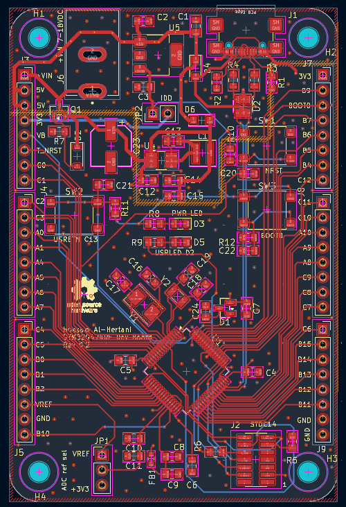
The development board is 2.2″ wide by 3.3″ long 4-layer design. I opted to go with 6*8 pin 0.1″ headers for the I/O, due to ease of availability of 8-pin stacking headers, as I already have two daughterboards that I plan to stack above it.
Demo
I built a smart environmental monitoring system with this board. In addition to this microcontroller board, the smart environmental monitoring system included:
- SENSEVAL-SCB4XV1 DIL 24 evaluation board from Sensirion that included a temperature and humidity sensor (SHT4x), VOC sensor (SGP40) and a barometric pressure sensor (LPS22DF)
- MSP4031 4.0″ SPI TFT LCD screen (ST7796) with integrated capacitive touch sensing (FT6336U)
I used the STM32HAL C libraries along with LVGL 8.4 and FreeRTOS to develop working firmware.
Complete KiCad board design files, including JLCPCB Gerbers and assembly files can be found here