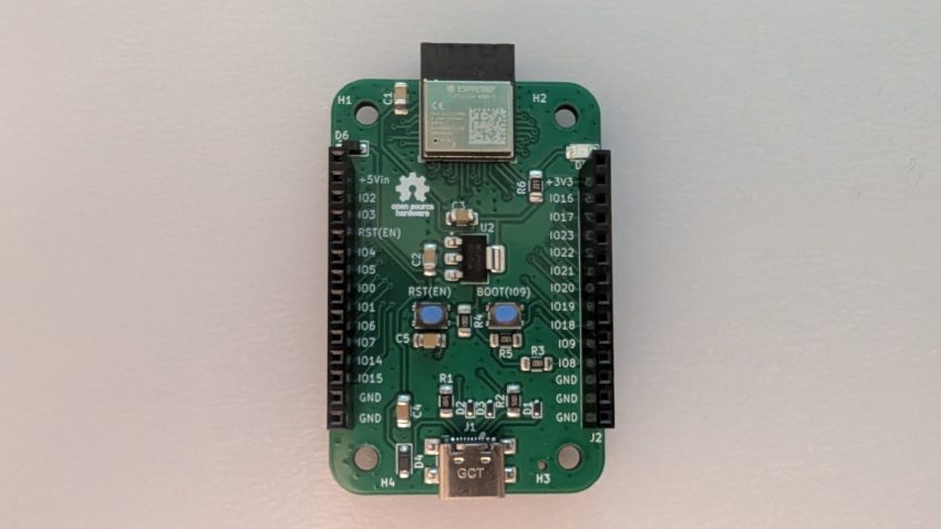
In this blog entry, I will introduce my IO uHat for the Raspberry Pi Zero 2W. This particular uHat provides: The IO uHat also hosts an I2C EEPROM as per the uHat specification. The configuration of this EEPROM will be covered in a future entry. The schematic is shown below: Both the GPIO expander and…
Interfacing an HD44780 Character LCD to a Raspberry Pi Zero 2W using Linux kernel drivers
This blog entry demonstrates how to interface an HD44780 character LCD to a Raspberry Pi Zero 2W, using Linux kernel drivers. This approach should also work on other Raspberry Pi single-board computers. Configure and load the HD44780 kernel module at boot First, you’ll need to load the correct HD44780 Linux kernel module. This will only…
IOTIS Daughterboard: 16 Channel Servo Motor Controller
The 16-channel servo motor controller is yet another IOTIS daughterboard reference design. It is based around the PCA9685 Pulse Width Modulation (PWM) controller integrated circuit (I.C.). The PCA9685 has 12-bit resolution. It can control up to 16 LEDs. Thanks to its ability to output a variable frequency ranging from 1526Hz to 24Hz, it can also…
IOTIS Daughterboard: Dual H-Bridge Motor Controller for Brushed DC Motors
The objective of the IOTIS ecosystem is to provide a standardized platform for students to develop their capstone projects. The baseboard and the powerboard are typically made available to all students. The students would then have to build their own daughterboard, which is application-specific to their particular capstone project and its requirements. The layout of…
The IoT Innovation Station
The EET Faculty at our college decided to develop a standardized printed circuit board (PCB) platform that students can utilize in their capstone projects. It’s called the IoT Innovation Station (IOTIS), and is sometimes referred to as the ‘IoT stack’. In addition to serving as a standardized platform for the program’s capstone project, students get…
PCB Layout Design with KiCad Part II: Layout Creation
In this blog entry, the PCB layout for the astable multivibrator circuit schematic design covered in part I, will be created using the Kicad PCB Editor application. Before proceeding however the user must be made aware of the two most common measurement units and how to convert between them. Importance of spatial dimensions and units…
PCB Layout Design with KiCad Part I: Introduction & Schematic Capture
In this blog entry, I will introduce the printed circuit board (PCB) design flow. I will then proceed to focus on the schematic capture section of the PCB design flow by using the KiCad PCB design tool to create a schematic for a simple LED blinker circuit. The PCB layout section of the design flow…
MicroPython Library for the PCA9685
The PCA9685 chip is a 16 channel PWM controller with 12-bits of resolution. It can control via PWM up to 16 LEDs. Thanks to the fact that it can output a variable frequency from 1526Hz down to 24Hz, it can also be used to control up to 16 servos. Servos usually expect a 50Hz signal…
UDPNode: A C++ class for UDP Communication
A couple of months ago, I decided to pursue few IOT project ideas that could benefit from basic UDP (User Datagram Protocol) communication. The MQTT and CoAP protocols are definitely more robust and secure. But there are some situations where the basic UDP protocol is sufficient. The POSIX C socket API built into Linux is…
Introducing PCBBot!
The PCBBot leverages the PCB itself as the robot chassis. This reduces cost significantly. It also means that the two motors and the caster wheel would have to be mounted on the PCB itself, in addition to the batteries and all the other components.


