PCBBot is our first attempt at building a custom mobile robot platform / kit for our students that:
- Consists (mostly) of through hole components that can be soldered by our students in their sophomore year
- Hosts the same ESP32-S3 microcontroller platform that we use in our programming classes
- Utilizes an array of sensors (inputs) and motors (outputs)
- Serves as a great tool to introduce students to embedded programming, software/hardware interfacing and troubleshooting, PCB hardware design and soldering.
- Is cost effective
The Design
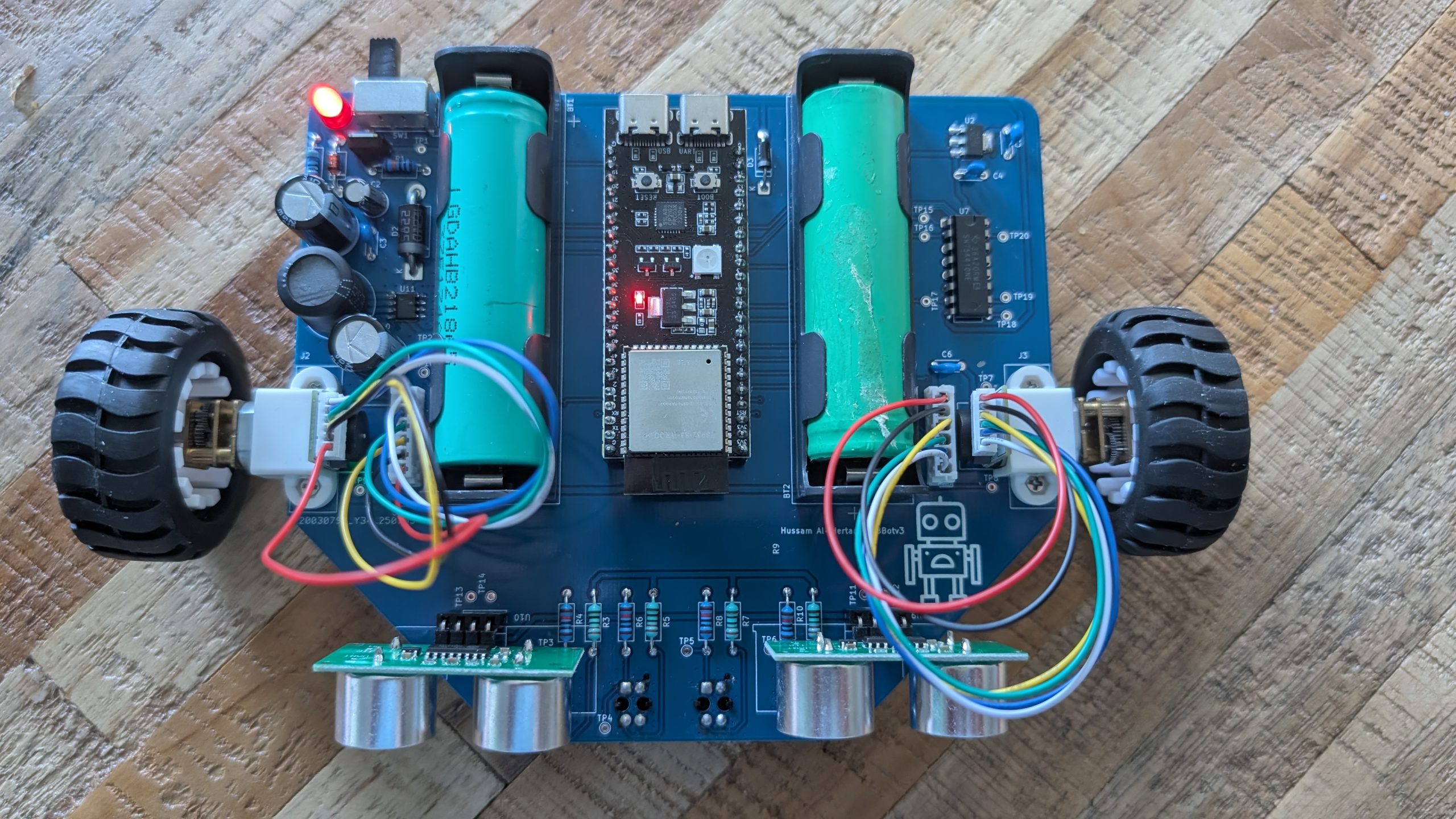
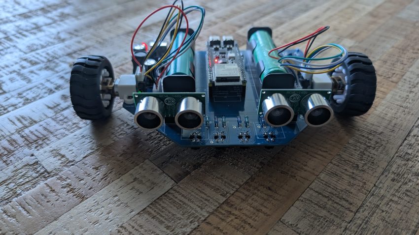
The PCBBot leverages the PCB itself as the chassis. This reduces cost significantly. It also means that the two motors and the caster wheel would have to be mounted on the PCB itself, along with the batteries and all the other components.
The Microcontroller
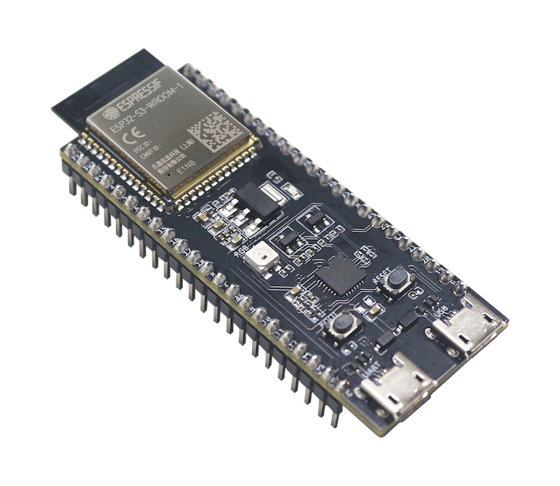
We decided to leverage the current microcontroller board that our students were using in their programming classes. The ESP32-S3 devkitc-1 board . The official development board can be purchased from Digikey for around $23-$25 CAD. You can find clones however of the board on Amazon and Aliexpress costing $10-13 CAD. While the ESP32-S3 module itself is definitely not a through hole component, the ESP32-S3 devkitc-1 board does come with two headers on its sides with 0.1″ pitch and fits nicely onto a breadboard. The board is large. A future iteration of the board may use a different ESP32-S3 dev board like this one here or here or here
The Batteries
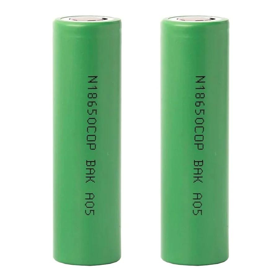
For power, we decided to go with two Lithium ion 18650 batteries in series. This gives us 7.4V-8.4V with on average current capacity of 2200mAH. This provides enough voltage and current to power our current setup and future upgrades should we choose to utilize beefier motors or a more power hungry computing platform such as the Raspberry Pi Zero 2W.
The downside is that good 18650 Lithium-ion batteries are expensive. Many also do not come with a protection circuit and are a fire hazard. I recommend buying 18650 batteries with a protection circuit or lithium iron phosphate LiFeP04 versions to mitigate risks. A future add on to the robot could be an LCD display that monitors the voltage across each battery.
The Motors
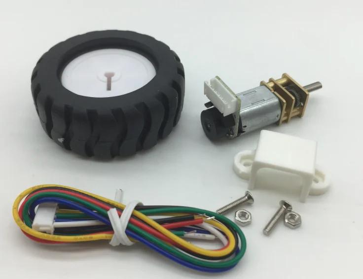
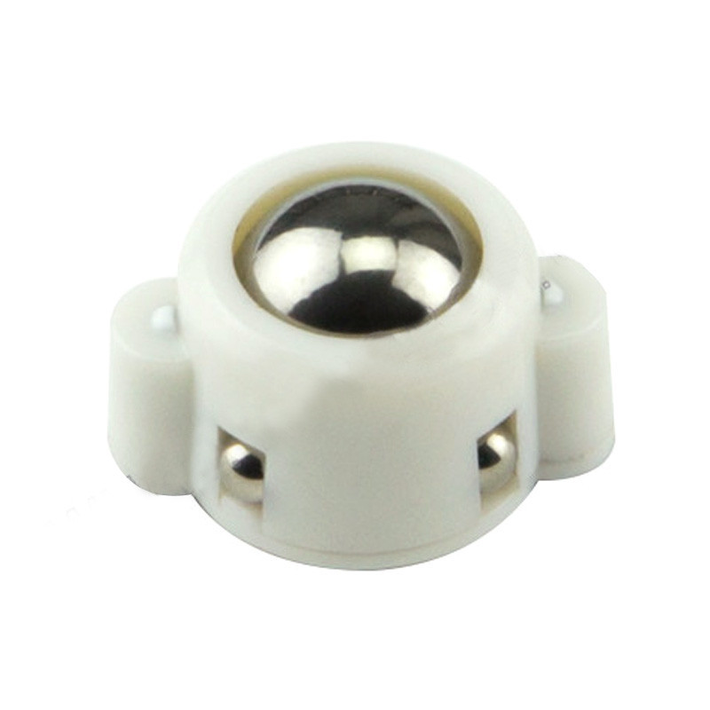
We decided to go with the 6V 100RPM N20 motors. You can get these with a built-in encoder, wheel and a motor bracket for under $15 CAD a pop on Aliexpress. If you choose to forgo the encoder, they can cost even less. The “Ball Caster 3PI N20 3/8″ ” is a caster wheel that nicely matches the N20 motors and their standard wheel size. The N20 motor with encoders comes with an additional connector for hooking up the encoders. The pins on the connector are all routed to general purpose input output (GPIO) pins on the ESP32-S3 to facilitate reading the encoder data in software.
The Motor Controller
The SN754410NE motor controller integrated circuit (IC) ticks a lot of boxes. It comes in a through hole package that contains two H-bridges and can be easily controlled via three GPIO pins per motor:
- MOTxA & MOTxB control the state of each motor i.e. coast, break, clockwise movement, counterclockwise movement.
- MOTxEN can act as either an enable pin or a pulse width modulation (PWM) pin that controls the average voltage placed across the motor and hence its speed.
The SN754410NE can handle up to 1A per motor and up to 36V. The N20 motors are rated for 6V and a no-load current of 40mA. Their stall current is around 210mA. So the SN754410NE should have no issues driving the N20 motors.
The Sensors
In addition to the motor encoder sensors built into the motors, the robot comes with four bottom mounted photo-reflective sensors (TCRT5000) that can be used for line following, and two ultrasonic range finding sensors (HC-SR04) used for obstacle avoidance.
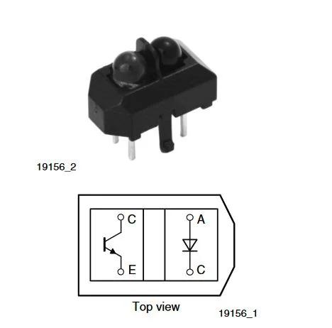
The TCRT5000 consists of an infra-red (IR) LED and a photo-transistor. The LED is constantly ON. The output signal coming from the photo transistor is an analog voltage whose magnitude is a function of how much light is reflected back onto the photo-transistor. For example. when the sensor is above black electrical tape, a significant portion of the IR light from the LED will be absorbed by the tape and not reflected back onto the photo-transistor, causing the photo-transistor to turn OFF and the analog output voltage will be close to the voltage rail (3.3V). When the sensor is above a white/bright background, a significant portion of the IR light from the LED will be reflected back on the photo-transistor causing the photo-transistor to turn ON and the analog output will be a small voltage (close to 0V). The sensor information from the TCRT5000 is read via an analog GPIO pins connected to the ESP32-S3’s analog to digital converter (ADC).
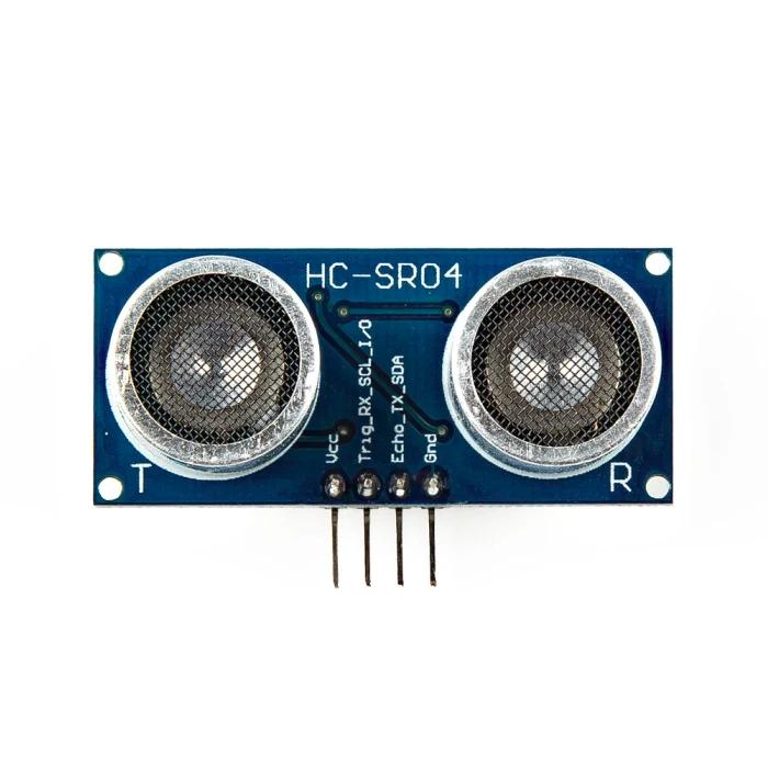
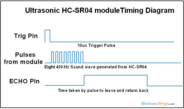
Each HC-SR04 range finding sensor requires two GPIO pins to interface with the ESP32-S3 microcontroller.
- Trigger pin (digital output) – Set this pin high for 10us to initiate emitting an ultrasonic pulse.
- Echo Pin (digital input) – Once the trigger pin is ‘pulsed’ , wait until this (echo) pin goes from low to high. Once high, start timing the pulse on the echo pin until it goes low. This pulse time is equivalent to the time it took for the ultrasonic wave to get to the closest object and bounce back to the sensor. If you take this time period, divide it by 2 and multiply it by the speed of sound, you’ll get the distance to the nearest object. The HC-SR04 can measure distances between 2cm and 400cm with a ranging accuracy that can reach up to 3mm.
Voltage Regulation Circuitry
Two 3.7V 18650 batteries connected in series are used to power the robot. The raw voltage from the batteries is nominally 7.4V(3.7V+3.7V) , but can be as high as 8.4V (4.2V+4.2) when fully charged. This battery voltage is applied across the motor rails (VCC). The battery voltage is then routed to an AP1509 5V switching buck regulator, which generates a 5V rail that powers the ESP32-S3 devkitC-1 development board, the logic rail on the motor controller IC and the IR LED portion of the TCRT5000. This buck regulator was chosen because it’s able to efficiently drop the supply down from 8.4V/7.4V to 5V. It is also able to supply up to 2A of current. This may seem excessive, but keep in mind that powering the IR LEDs in the TCRT5000s alone consume 64mA of current. The ESP32-S3 max current consumption when WiFi is in use can also be as high as 340mA. Having 2A amps of current room is nice, especially if we decide to upgrade the ESP32-S3 microcontroller to a more power hungry single board computer like the Raspberry Pi Zero 2W.
The regulated 5V supply is then routed to the LM1117 3.3V linear regulator, to provide a clean 3.3V rail used to power the photo-reflective (TCRT5000) sensor’s receiver end and the ultrasonic sensors.
A reverse polarity protection circuit, power indicator LED and a slide switch are also added to the circuit. You can view them in the schematic below.
The voltage regulators used on the PCBBot (AP1509 and LM1117-3.3) were the only surface mount components used in the design.
The Schematic
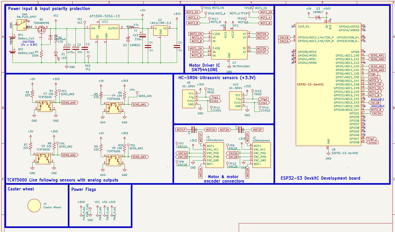
The batteries power the motor rail (VCC) directly. The motor rail is then routed to a 5V regulator to derive the 5V rail. The 5V rail is then routed to a 3.3V regulator to derive the 3.3V rail.
A Schottky diode is used on the 5V input pin on the ESP32-S3 devkitc-1 development board to ensure that 5V goes only into the development board and not come out of it when using the USB ports.
Overall, a total of 18 GPIOs where required:
- 6 pins for motor control
- 4 pins for the motor encoders
- 4 pins for the ultrasonic sensors
- 4 pins for the line following (photo reflective sensors)
Care was taken when choosing the GPIO pins to use. The following pins were avoided as they have other uses that could limit their functionality or make them completely unavailable:
- Cannot use: GPIO26-32 (Flash), power/ground pins, USB pins (19,20)
- Limited use: GPIO0 (external 10kΩ pull-up ), GPIO3, GPIO45, GPIO46 (external 10kΩ pull-down) (strapping), GPIO43/44 (UART0)
- JTAG pins: GPIO39-42 (can use if JTAG not needed)
- PSRAM pins (if present): GPIO33-37 (cannot use on PSRAM variants)
For PSRAM variants of the ESP32-S3 devkitc-1 board, the truly “safe” GPIO pins are significantly reduced to: GPIO1, GPIO2, GPIO4-GPIO18, GPIO21, GPIO38, GPIO47, GPIO48. The 18 GPIOs the PCBbot uses were selected from this list of pins.
The PCB Layout
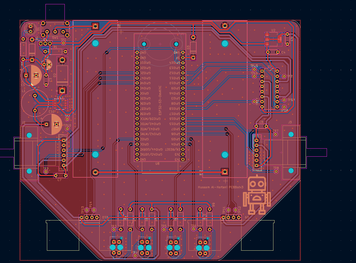
The PCBBot PCB layout was developed on a 14cm by 12cm 2-layer board with the trapezoidal shape shown above. PCB Footprints were created from the motors, motor brackers, and caster wheel to ensure that they can be accurately mounted on the PCB.
Given that the design predominantly used through hole components some of the routing was a little inefficient. But was able to pass the DRC with no errors.
Make one yourself
I’ve made my PCBBot KiCAD PCB design freely available on my Github page along with a Digikey bill of materials (BOM) (caster wheel, motor brackets and motors not included) and MicroPython code. I’m also providing my custom symbol and footprint libraries. Feel free to make your own version of the PCBBot as is or modify it to suit your needs. Have fun!