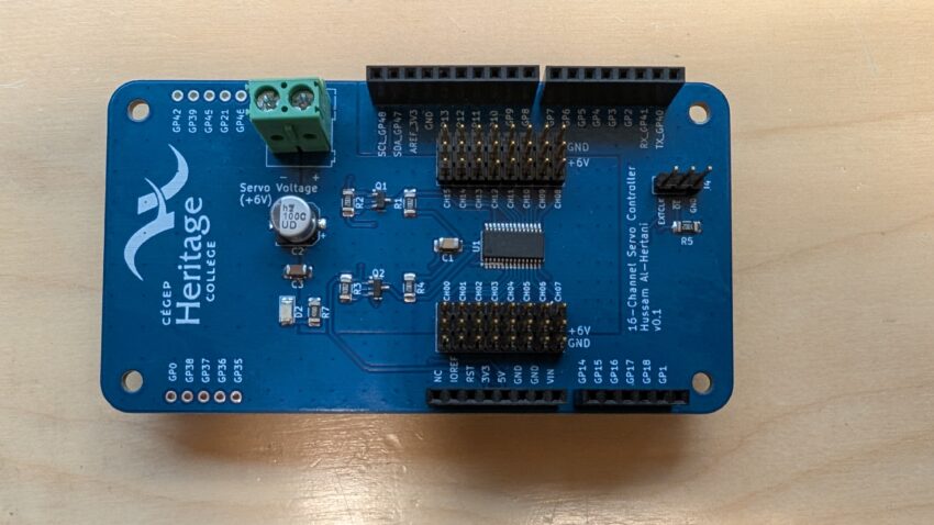
The 16-channel servo motor controller is yet another Arduino shield-compatible, IoTIS daughterboard reference design. It is based around the PCA9685 Pulse Width Modulation (PWM) controller integrated circuit (I.C.). The PCA9685 has 12-bit resolution. It can control up to 16 LEDs. Thanks to its ability to output a variable frequency ranging from 1526Hz to 24Hz, it can also be used to control up to 16 servos. Servos usually expect a 50Hz signal (20ms period). The angular position of the shaft is a function of the ON time. For many standard servos:
- 1.5ms ON time moves the shaft to the 0 degree position.
- 1ms ON time moves the shaft to the -90 degree position.
- 2ms ON time moves the shaft to the +90 degree position.
The exact ‘ON’ time differs across different types of servos, but the PCA9685 should be able to handle the various timing requirements demanded by most servos.
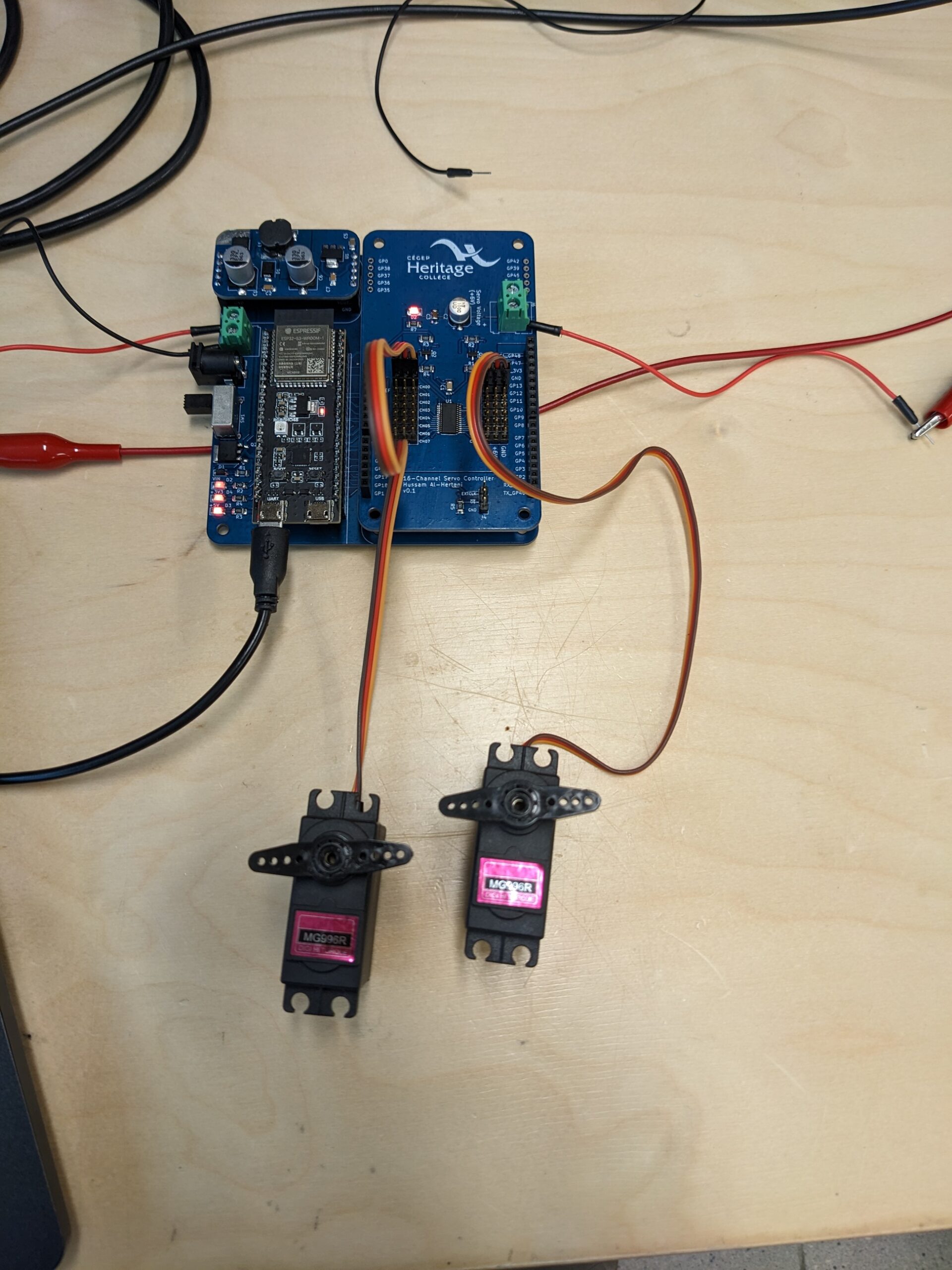
I also wrote a PCA9685 MicroPython library that facilitates controlling the PCA9685 chip from the ESP32S3 microcontroller via the I2C bus. The library contains all the high-level servo control functions needed to control up to 16 servos at once.
The 16-Channel servo controller daughterboard Schematic
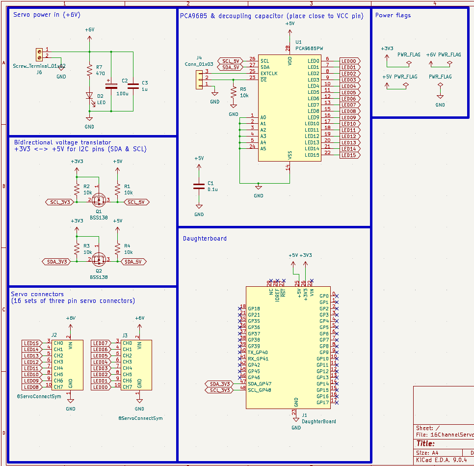
The design schematic is shown in Figure 2. Servo power is routed directly onto the daughterboard via the J6 terminal block. Most servo motors are powered by 6V-8.4V. In addition to the servo power rail, servos also require a logic-level servo signal, whose voltage needs to be +3.3V/+5V. Some servos still work with only the +5V servo signal voltage. To allow for maximum compatibility across servos, I decided to power the PCA9685 chip with +5V; therefore, the PWM / pulsed signals it generates are all +5V.
The ESP32S3 microcontroller is a +3V3 device. To allow interfacing a +5V I2C device to a +3V3 microcontroller, a MOSFET-based bidirectional voltage translator circuit (Q1 & Q2) was used to translate the +3V3 SDA, SCL signals on the ESP32S3 side to +5V SDA and SCL signals on the +5V-powered PCA9685 side. This simple voltage translator circuit works quite well.
The remainder of the circuit is straightforward. 2 8×3 (2.54mm pitch) servo connector headers were included. These bring out all the PCA9685’s 16 PWM pins along with servo power and ground rails.
The output enable (OE) signal from the PCA9685 is pulled to ground via a pulldown resistor and brought out to a header.
The external clock signal (EXTCLK) is also brought out to the same header. This pin allows the user to replace the PCA9685’s internal 25MHz oscillator with an external one if additional accuracy is required.
Finally, the PCA9685’s I2C pins are connected to the daughterboard’s I2C pins (GPIO47 & GPIO48) via the bidirectional voltage translator circuit.
The 16-Channel Servo Controller Daughterboard PCB Layout
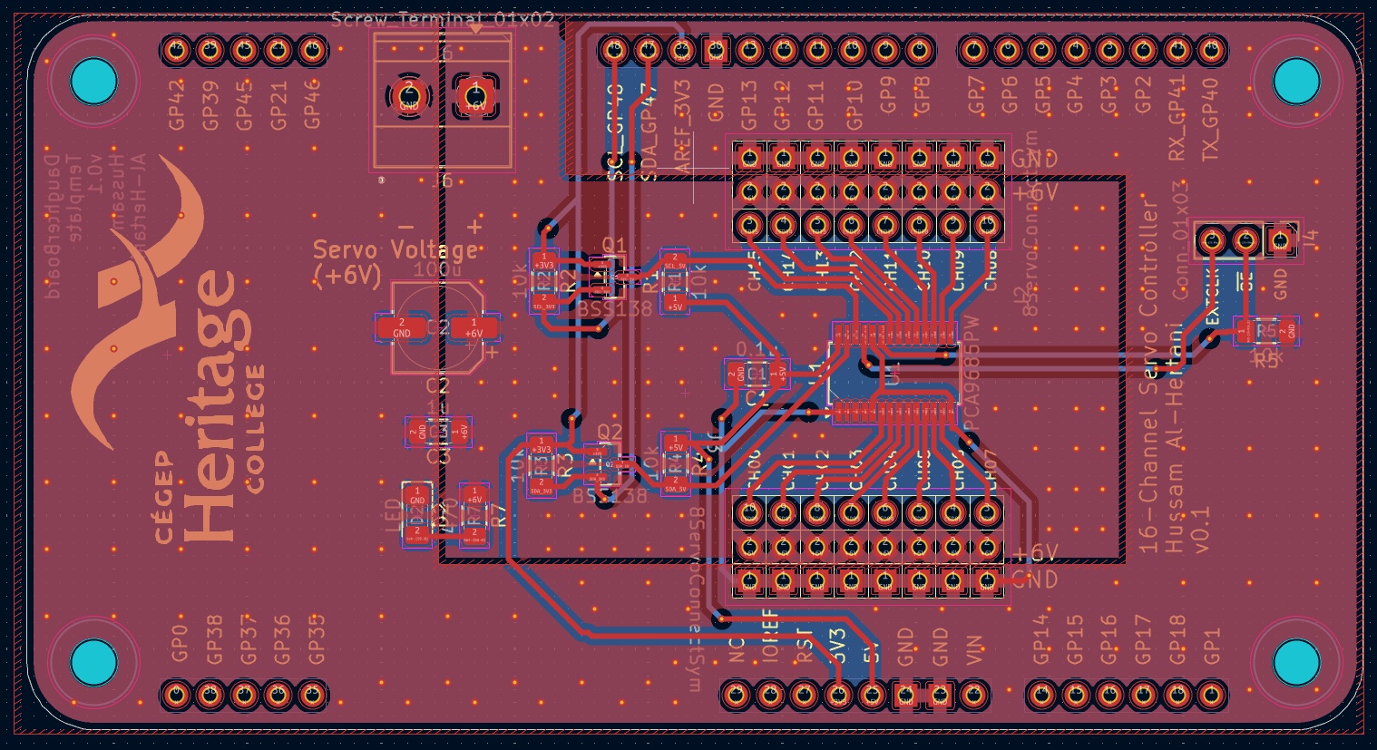
The layout for the design is shown in Figure 3. I utilized a ‘zone’ approach for the servo power and ground rails. The zone in the middle is the servo power zone and is present on both the top and bottom copper layers. The zone surrounding this middle zone is the ground zone/copper fill. It too is present on both layers of the board. This ‘zone’ approach is good for maximizing current delivery into the servos and improving the board’s thermals, especially when it’s being used to control multiple beefy servo motors.
The complete KiCad files for this daughterboard are available here. My KiCad library containing the daughterboard symbol and empty footprint outlines is also available.